

Jointing Components with Ductile Iron Flanges (PVC)
The following procedure should be adopted for jointing pipeline components with flanges complying with AS 4087 and gaskets complying with WSAA Industry Standard for Flange Gaskets and O-rings, WSA 109.
Jointing Procedure
- Thoroughly clean the flange faces to be jointed, ensuring there is no dirt, particles of foreign matter, protrusions or coating build-up on the mating surfaces. Use a scraper or wire brush to remove any irregularities.
- Ensure that the mating threads of all nuts and bolts are clean and in good condition.
- Evenly apply a suitable lubricant to all mating threads, including the nut load bearing face.
- Align the flanges to be jointed and ensure that the components are satisfactorily supported to avoid bending stress on the flanged joint during and after assembly.
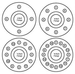
- Insert four bolts in locations 1 to 4 as indicated on the Figure below and position the insertion gasket on the bolts, taking care not to damage the gasket surface. Alternatively, locate the O-ring in the machined groove of the flange.
- Offer the adjoining flange to the bolts, taking care to maintain alignment and support of the components.
- Tighten nuts to finger tight and check alignment of flange faces and gasket.
- Insert the remaining bolts and tighten nuts to finger tight.
- Determine the required bolt tension and the estimated torque from the Table.
- Tighten nuts to 30% of estimated torque using the star pattern detailed on the Figure below.
- Tighten to 60% of estimated torque using the same tightening sequence.
- Tighten to 100% of estimated torque using the same tightening sequence.
- Finish with one final pass, tightening to 100% of estimated torque in a clockwise direction.
Estimated Tightening Torque Values
Required bolt tensions and estimated torques have been assessed using established engineering principles. However, variation in installation procedures may result in different requirements.
The estimate torques provided in the Table below are based on the coefficients of friction (µ) indicated. Where other coefficients apply, alternative torques should be calculated. “Lightly Oiled” refers to the application of a good quality lubricating oil and is the usual as received condition of fasteners.
“Well-lubricated” refers to the application of molybdenum disulphide grease, or equivalent anti-seize compound.
This Table has been reproduced from WSA 109 and applies to the following:
- Standard Pressure Flanges AS 4087 Figure B5 Class 16
- Grade 4.6 galvanised steel bolts and nuts or Class 50 Grade 316 stainless steel bolts and nuts as indicated
- Full faced gasket 3mm EPDM seal
| Nominal Size | Bolt Size | Number of Bolts | Length of Bolts | Bolt Tension | Torque | ||
| Lightly Oiled Grade 4.6 galvanised steel bolts and nuts µ = 0.22 |
Well lubricated Grade 4.6 galvanised steel bolts and nuts µ = 0.15 |
Well lubricated Grade 316 Class 50 stainless steel bolts and nuts µ = 0.20 |
|||||
| DN | (mm) | kN | Nm | Nm | Nm | ||
| 80 | M16 | 4 | 65 | 20 | 70 | 40 | 65 |
| 100 | M16 | 4 | 75 | 20 | 70 | 55 | 65 |
| 150 | M16 | 8 | 75 | 20 | 70 | 40 | 65 |
| 200 | M16 | 8 | 75 | 20 | 70 | 55 | 65 |
| 225 | M16 | 8 | 75 | 25 | 90 | 60 | 80 |
| 250 | M20 | 8 | 90 | 35 | 160 | 105 | 140 |
| 300 | M20 | 12 | 100 | 35 | 160 | 85 | 140 |
| 375 | M24 | 12 | 100 | 50 | 270 | 150 | 240 |
| 450 | M24 | 12 | 120 | 55 | 290 | 190 | 270 |
| 500 | M24 | 16 | 120 | 55 | 290 | 185 | 270 |
| 600 | M27 | 16 | 130 | 70 | 420 | 270 | 380 |
| 750 | M30 | 20 | 140 | 80 | 530 | 360 | 480 |
Notes:
- Grade 4.6 galvanised mild steel or Grade 316 property class 50 stainless steel bolts are proposed for joining Class 16 flanges.
- Grade 8.8 galvanised steel or Grade 316 property class 80 stainless steel stud bolts are proposed for joining Class 35 Flanges.
- Bolt tensions have been calculated to counter the force due to expected internal pressure and to provide an adequate sealing stress on the nominated gasket material, without exceeding the maximum allowable gasket stress at the time of installation. The necessary torques to induce these tensions are estimated for raised face flanges with common surface finishes used in the Water Industry.
- The application of excessive torque at the time of installation may overstress the gasket causing crushing or extrusion, which can lead to leakage at operating pressures.
- The surface conditions of the threads as a result of rust, plating, coating and lubrication are the predominant factors influencing the torque/tension relationship. However, there are many others including thread fit, surface texture and the speed and continuity of tightening.
- The flange faces are assumed to have a surface roughness of Ra=10-12.5 µm.
- A torque wrench is most commonly utilised to achieve the required bolt tension, however in critical applications a hydraulic tensioner should be used.