

Maximum Allowable Operating Pressure (MAOP) for PE Pipes
Vinidex PE pipes are manufactured to AS/NZS 4130.
Series 1 water pipes have wall thickness and pressure ratings determined by the Barlow formula as follows:
T =PD/ 2S + P
where:
Series 1 fuel gas pipes are classified in accordance with SDR.
Hydrostatic Design Stress
The design of AS/NZS 4130 pipes has been based on the static working pressure operating continuously at the maximum value for the entire lifetime of the pipeline. The value of maximum hoop stress used in the selection of the pipe wall thickness is known as the Hydrostatic Design Stress (HDS). This value is dependent upon the type of PE material being used and the pipe material service temperature.
In AS/NZS 4131, materials are classified for long term strength by the designation Minimum Required Strength (MRS). The MRS is the value resulting from extrapolation of short and long term tests to a 50 year point at 20°C.
Note: See Polyethylene Properties for typical stress regression curves.
The Hydrostatic Design Stress (HDS) is obtained by application of a Design or Safety Factor (C) to the MRS. See the table below.
HDS = MRS/C
The specific value selected for the Design Factor depends on a number of variables, including the nature of the transmitted fluid, the location of the pipeline, and the risk of third-party damage.
The wall thickness values for Series 1 pipes to AS/NZS 4130 were derived using a value of 1.25 for C, this being the minimum value applicable.
AS/NZS 4131 specifies MRS values of 8.0 MPa and 10.0 MPa for the grades designated as PE 80 and PE 100 respectively. The relationship between the HDS and MRS standard values in AS/NZS 4131 is as shown in the Table below. These standard values are polymer dependent and long-term properties for each pipe grade material are established by long term testing to the requirements of ISO/DIS 9080 by the polymer producers. Individual PE grades may exhibit different characteristics and PE materials can be provided with enhanced specific properties. In these cases, the advice of Vinidex engineers should be obtained.
Hydrostatic Design Stress and Minimum Required Strength Values
| Material Designation | Minimum Required Strength (MRS) | Hydrostatic Design Stress (HDS) |
| MPa | MPa | |
| PE 80 | 8 | 6.3 |
| PE 100 | 10 | 8 |
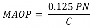
Maximum Allowable Operating Pressure
The Maximum Allowable Operating Pressure is given by:
For Series 1 Water and Sewerage pipes:
 For Series 1 Gas pipes:
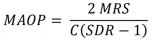
where:
For example, if the minimum value of C is chosen (C = 1.25), a PN 10 pipe will have a MAOP of 1.0 MPa at 20°C. PE pipe pressure ratings based on C=1.25 are given in the Table below.
PE Pipe Pressure Ratings
| Pressure Class | Nominal Working Pressure | |
| PN | MPa | metres head |
| 3.2 | 0.32 | 32 |
| 4 | 0.4 | 40 |
| 6.3 | 0.63 | 63 |
| 8 | 0.8 | 80 |
| 10 | 1 | 100 |
| 12.5 | 1.25 | 125 |
| 16 | 1.6 | 160 |
| 20 | 2 | 200 |
| 25 | 2.5 | 250 |
Where pipes are used for drinking water applications with higher disinfectant residuals, particularly at elevated temperatures, further consideration may be required. See Chemical Resistance of PE Pipes.
The following table shows the Minimum design factors for PE pipes in various applications.
| Pipeline Application | Design Factor |
| 20°C | C |
| Water Supply | 1.25 |
| Natural Gas | 2 |
| Compressed Air | 2 |
| LPG | 2.2 |
Where pipes are used to carry fluids other than water or in certain conditions where the consequences of failure are particularly significant, then another value of the Design Factor may need to be selected. The value selected will depend on both the nature of the fluid being carried and the location of the pipeline installation.
The Design Factor is a combination of sub factors (ƒx) which must be factored together to give the final value for C such that C is not less than the values for minimum design factors tabulated above, and:
C = ƒ0 x ƒ1 x ƒ2 x ƒ3
Design Factors for water and sewage pipe systems
The table below is reproduced from AS/NZS 4130 and gives advisory information on selection of Design Factors for water and sewerage pipes.
| Installation Conditions | Design factor | Value | |
| Fluid Type | Water | ƒ0 | 1.25 |
| Domestic Sewerage | 1.25 | ||
| Industrial Sewerage | 1.25 | ||
| Soil, fluid or pipe Temperature (Av.°C) | -20 < t ≤ -10 | ƒ1 | Refer Vinidex |
| -10 < t ≤0 | 0.6 | ||
| 0 < t ≤ 20 | 1 | ||
| 20 < t ≤ 30 | 1.1 | ||
| 30 < t ≤ 35 | 1.25 | ||
| 35 < t | Refer Vinidex | ||
| Location based on minimum depth of cover specified in AS/NZS 2566.1 | Open field | ƒ2 | 1 |
| Minor country road shoulder | 1 | ||
| Major country road shoulder | 1 | ||
| Minor country road – under pavement | 1.1 | ||
| Major country road – under pavement | 1.2 | ||
| Residential paved and unpaved nature strip | 1 | ||
| Residential roadway – under pavement | 1.1 | ||
| Major urban roadway – under pavement | 1.2 | ||
| Commercial/Industrial paved and unpaved nature strip | 1.1 | ||
| Commercial/Industrial roadway – under pavement | 1.2 | ||
| Central Business District | 1.4 | ||
| Private land – easement | 1 | ||
| Above ground | 1 | ||
| Submarine crossings | 1.4 | ||
| Installation method | Standard trenching | ƒ3 | 1 |
| Plough-in | 1.1 | ||
| Directional drilling | 1.2 | ||
| Slip line with back grouting | 1 | ||
| Slip line without back grouting | 1.2 | ||
| Pipe cracking with liner pipe in situ | 1 | ||
| Pipe cracking with liner pipe removed | 1.1 | ||
| Pipe cracking without liner pipe | 1.2 | ||
Design Factors for gas pipes
The table below is reproduced from AS/NZS 4645.3 and gives advisory information on selection of Design Factors for gas pipes.
| Installation Conditions | Design factor | Value | |
| Fluid Type | Natural Gas | ƒ0 | 2 |
| LPG | 2.2 | ||
| Operating Temperature (Av.°C) | -20 < t ≤-10 | ƒ1 | Refer Vinidex |
| -10 < t ≤ 0 | 1.2 | ||
| 0 < t ≤ 20 | 1 | ||
| 20 < t ≤ 30 | 1.1 | ||
| 30 < t ≤ 40 | 1.3 | ||
| Installation method | Open trench with padding | ƒ2 | 1 |
| Other | 1.1 | ||
| Population Density | Open field area | ƒ3 | 0.9 |
| Residential area | 1.05 | ||
| High density community use | 1.2 | ||