

PRO Jointing
Joint Details
StormPRO® and StormFLO® pipes have a simple and effective rubber ring joint system which is easy to assemble, leak-tight and protects against tree root intrusion.
Vinidex PRO2 is a new jointing system designed for easier installation and leak tight joint performance. The PRO2 joint design uses a new redesigned rubber ring to match new socket geometry. Ensure that only PRO2 rubber rings are used with PRO2 sockets. PRO2 sockets can be identified by a label on the socket and PRO2 rubber rings can be identified by PRO2 marking on the ring.
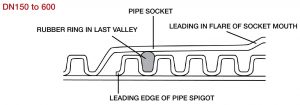
For DN150 to DN600 pipes, the rubber ring is located on the spigot in the last valley between the corrugations.
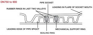
For DN750 and DN900 pipes, two rings are used and are located in the first two valleys. The ring in the first valley is the sealing ring whereas the second ring is a mechanical support ring which has the dual benefit of providing redundant sealing capacity.
The Figure below shows the joint details in cross section.
For sizes DN150 to DN600, the pipe can be cut to length, as required, anywhere along the barrel and the same jointing system used.
The spigot ends on pipe sizes DN750 and DN900 are geometrically different to the main pipe barrel. Where these pipe sizes need to be cut to length, couplings must be used for jointing. This system is suitable for occasional use but is not recommended for routine jointing. If many shorter pipe lengths are required, contact Vinidex to discuss an alternative solution.
No chamfer is required.
Jointing Procedure
Installation: Pipe Jointing Video
For the full range of installation videos, please view our Stormwater and Underground Drainage Product Support Page.
Resources
For the jointing procedure for PRO and FLO pipes, please refer to the Stormwater and Underground Drainage Systems Product Support area.
Angular Deflection
The pipe may be deflected at the joint after jointing has been completed. Any deflection should be limited to a maximum of 1º.
Witness Mark
The rubber ring is held in position by the corrugations on the outer wall of the pipe. When the joint is assembled, the inner walls of the pipe butt together so it is not necessary to joint to a witness mark in the same way as it is for pipe joints designed with a laying gap. However, if required as a visual indication of correct jointing depth, a witness mark can be applied to the spigot end. Depending on manufacturing tolerances, a witness mark on the crest of the 5th rib for sizes DN150 to DN300 and on the crest of the 4th rib for sizes DN375 to DN900 will be either wholly within the socket, or just visible at the mouth at the completion of jointing.
Internal Lining
When the pipe is pushed fully home during assembly, the spigot end and the internal lining at the back of the socket are generally in contact. However, due to manufacturing tolerances or where there is angular deflection at the joint, a small gap may sometimes be observed. This has no effect on the sealing capability of the joint.