

PVC Buckling
A pipe subjected to pressure externally (or vacuum internally) is subject to a potential stability problem. For any given diameter/wall thickness ratio, there is a critical collapse pressure at which the pipe wall will commence to buckle inwards. The failure mode is unstable, i.e. the more it buckles the less resistance to buckling, and so total collapse occurs rapidly.
Situations where pipe buckling may arise are comparatively rare, but in certain circumstances this can be a controlling factor on selection of pipe class.
Unsupported Collapse Pressure
The unsupported critical buckling pressure sustainable by a pipe can be calculated from:
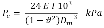
where:
This may also be expressed in terms of the pipe ring-bending stiffness as:
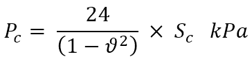
where:
Since the ring-bending stiffness is broadly constant for a particular class of pipe, the collapse pressure is independent of diameter and can be computed for each class. Note, however, that PVC-U pressure pipe to AS/NZS 1477 has different dimension ratios for small bore and large bore (DN 175 and over) pipes. Calculated minimum ring-bending stiffnesses are tabulated in the table below:
Minimum calculated stiffness, Sc, for PVC pressure pipes (kPa)
| PN | Material / Modulus (MPa) | |||||
| PVC<=150 3200 |
PVC>150 3200 |
PVC-M 3000 |
PVC-O 400 4000 |
PVC-O 450 4000 |
PVC-O 500 4000 |
|
| 4.5 | 2.3 | 1.6 | – | – | – | – |
| 6 | 5.4 | 3.9 | 2.6 | – | – | – |
| 9 | 18.3 | 13.1 | 4.3 | – | – | – |
| 12 | 43.3 | 31 | 10.1 | – | – | – |
| 12.5 | – | – | – | 5.2 | 3.7 | 2.5 |
| 15 | 84.5 | 60.5 | 19.7 | – | – | – |
| 16 | 102.6 | 73.4 | 23.9 | 10.9 | 7.8 | 5.2 |
| 18 | 146.1 | 104.5 | 34 | – | – | – |
| 20 | 200.4 | 143.3 | – | – | – | 10.2 |
Note: The stiffness values above are calculated on the basis of minimum wall thickness at any point. Since the stiffness is a function of the mean wall thickness, it is statistically not possible for these values to be realised in practice, and the real stiffness will be significantly greater. Based on known process capabilities the mean wall thickness could reasonably be expected to be at least 5% above minimum and the stiffness correspondingly 16% higher than the figures above.
The stiffness is related to the effective modulus, which varies with the loading condition (short or long term), and also with temperature. For long term loading and/or elevated temperatures, the critical buckling pressure should be multiplied by a correction factor to take the variation in modulus into account. Appropriate values of the temperature/loading time correction factor are given in the table below.
Temperature / Loading time Correction Factors
| Loading term | Temperature | ||
| 20°C | 30°C | 40°C | |
| Short Term – e.g. water surges (seconds/minutes) | 1 | 0.96 | 0.93 |
| Medium Term – e.g. concrete work (hours) | 0.81 | 0.75 | 0.66 |
| Long Term – (day/month) | 0.69 | 0.63 | 0.56 |
| Permanent- e.g. ground water (50 years) for PVC-U and PVC-M | 0.37 | 0.28 | 0.18 |
| Permanent- e.g. ground water (50 years) for PVC-O | 0.44 | 0.33 | 0.22 |
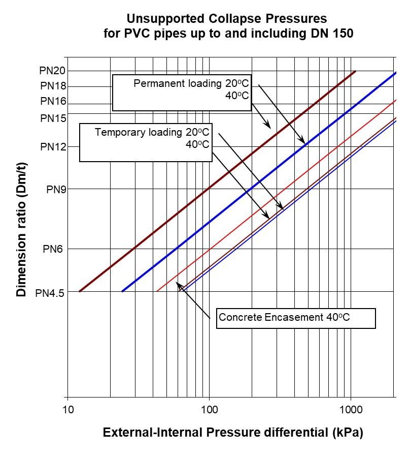
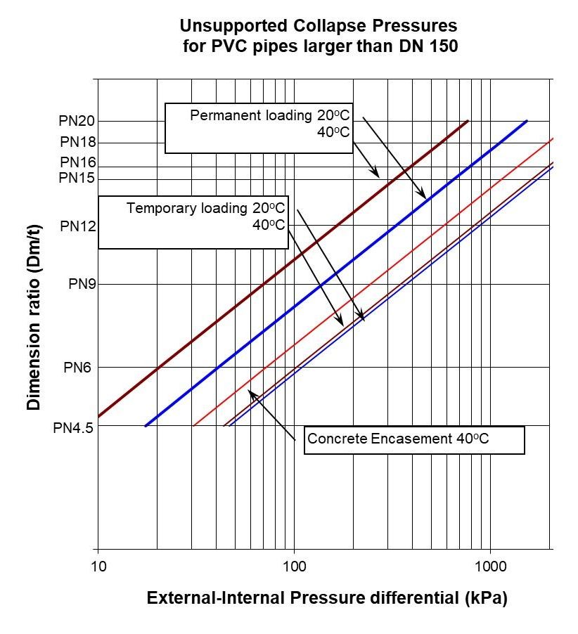
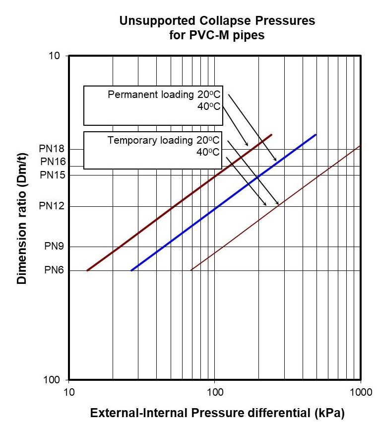
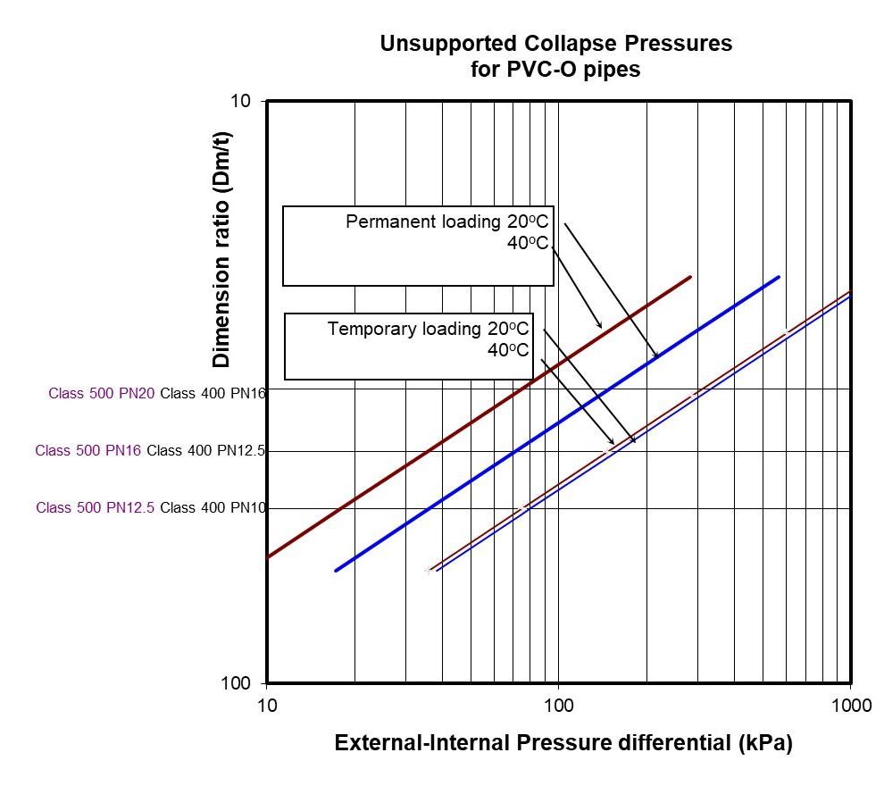
The critical collapse pressures for standard PVC-U, PVC-O and PVC-M pipes for a range of operating conditions are shown in the graphs below.
Note: Pipe wall thickness has a major influence on the critical buckling pressure. Therefore PVC-O and PVC-M pipes will not have the equivalent resistance to unsupported collapse as PVC-U pipes of the same pressure class.
Unsupported Collapse Pressures for PVC Pipes
Effect of Ovality
Initial ovality of a pipe will reduce the critical buckling pressure. The reduction can be calculated by multiplying the critical buckling pressure, Pc, by a correction factor, C1 which is calculated as follows:
For an oval pipe with,
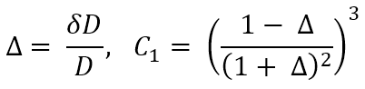
where:
Values for C1 are summarised in the following table:
| Diametral Deflection % | 0 | 1 | 2 | 5 | 10 |
| Reduction factor, C1, on Pc | 1 | 0.91 | 0.84 | 0.64 | 0.41 |
Note that these reductions apply to inherent initial ovality as distinct from induced ovality, i.e., where ovality has been induced by some external (constant strain) source, as in deflection induced by soil loadings, the pipe is already in a state of elastic strain, and the resistance to buckling is degraded far less. In this case, the correction factor C2 is used as given in the following table:
| Diametral Deflection % | 0 | 1 | 2 | 5 | 10 |
| Reduction factor, C2, on Pc | 1 | 0.99 | 0.97 | 0.93 | 0.86 |
Supported Collapse Pressure
Support against buckling is provided by end constraints, fittings or special purpose stiffening rings at intervals around the pipe. Effective support reduces as distance from a stiffened section increases and should be considered zero at a distance of seven diameters.
A buried pipe derives support against buckling from stable soil surround. The effective buckling pressure may be computed from:
![]()
Where E’ is the soil modulus in MPa. For values of E’, refer to AS/NZS 2566.1.
As for Pc, Pb should be multiplied by a temperature/loading time factor if required – see table 3.11.
For shallow burial, full support is not developed since buckling can occur by vertical lifting of the soil cover. AS/NZS 2566.1 specifies that for cover heights less than 0.5m, Pc be used to evaluate the potential for buckling. Where cover heights are greater than or equal to 0.5m, the greater of Pc and Pb should be used. In both cases, an appropriate factor of safety needs to be incorporated.
Factors of Safety
The equations and graphical representations predict actual collapse pressures. Except for the use of a theoretical calculated stiffness based on minimum wall, no factor of safety is incorporated and designers should decide on an appropriate factor based on service conditions, consequences of failure and predictive uncertainty.
AS/NZS 2566.1 specifies a factor of safety of 2.5 unless an alternative is specified by the designer. A lower factor of safety should only be specified where conditions and performance can be predicted with confidence. For example, in a calculation of unsupported buckling of a pipe under vacuum, a factor of 1.5 may be appropriate.
Examples of Class Selection for Buckling
- A PVC-U submarine sewer rising main DN 150 is to be laid across a lake. Inlet and outlet well levels are at lake maximum water level.
Internal and external static heads are more or less balanced under steady state conditions. However, negative surging on pump shut down is probable, resulting in up to 10 metres negative head differential. In view of the consequences of failure, a factor of safety of at least 2 is suggested. For short term conditions, a PN 6 pipe has Pc = 14 m and PN 9 P = 46 m. Use PN 9. - A DN 300 PVC-U line is laid in saturated clay alongside a tidal estuary at a depth of 4 metres. During construction or maintenance, the pipe may be empty.
Assuming a saturated soil density of 2000 kg/m3, an external pressure of 80 kPa is developed. This would be considered a permanent condition and a factor of safety of 3 is advisable. PN 9 has Pc = 8 m. Use PN 12. - A PVC-U irrigation pump suction line DN 200 is required to sustain continuous operation at -5 metres. Temperature of the supply can be up to 30°C during hot spells.
Unlike pressure rating where the average temperature is considered, peak conditions are significant for buckling. In this situation PN 9 has Pc = 10 m, giving a factor of safety of 2, which should be adequate. - A DN 150 PVC-U drainage pipe is to be encased in a concrete column. The maximum pour height will be 4 metres.
An SN4 DWV pipe (PN 6) can sustain 4 metres of concrete but has no factor of safety. Use Class SN8 DWV or PN 9 pressure pipe. Alternatively, fill the pipe with water during the pour. The net pressure differential is then 60 kPa and a factor of safety of 1.7 is provided on PN 6. Alternatively, pour in two stages, at least one hour apart. - A DN 150 PN 16 PVC-O 500 pipe is to be installed in an area where the in-situ material is sandy clay. The embedment material will be sand and cover height will be 1m. A water hammer analysis has shown that accidental event may result in a negative pressure of -9m. Check that in this case there is an adequate factor of safety against buckling. Using AS/NZS 2655.1 and the trench and soil conditions, an E’ value of 6.3MPa is derived. From the equation, Pb = 590 kPa. Therefore, there is an acceptable factor of safety.