

PVC pipes under external pressure (VX-TN-4F)
Introduction
A pipe subjected to pressure externally (or vacuum internally) is subject to a potential stability problem and can undergo a form of unstable collapse if the pressure is sufficiently high, through buckling of the pipe wall.
Such conditions apply when an unpressurised pipe is surrounded by water or concrete, or when vacuum is applied to a tube.
Buried pipes receive support from the soil greatly increasing their collapse pressure. However they can be subjected to higher external pressure from the overburden and design checks for stability should be carried out.
The purpose of this note is to discuss such applications, outline the theoretical considerations involved, and recommend design procedures.
Applications
Some of the practical situations where this can occur are:
- Tube immersed in water: For example a stand pipe or overflow in a reservoir, a pipe laid under water or storm drains which may be subject to external flooding.
- Concrete surround: The problem can arise during installation of concrete encased pipe and void forms. Although concrete has some shear strength it must be assumed to have nil during vibration the pressure of concrete may be calculated as: 25 x concrete depth (kPa), where the concrete depth is measured in m from the centre of the tube.
- Sewer relining: In this case, a positive head of ground water may build up around the liner pipe. Because of irregularities in the original pipe, some annular gap must exist between the original and liner pipe, and a condition of zero support must, in general, be assumed.
If positive external heads are likely, the stiffness of the liner pipe must be sufficient to cope with the situation, or the system must be grouted with cement or polyurethane foam. Grouting of any type will provide the necessary support and guard against unstable buckling.
However, the process of applying grout needs careful consideration since grouting pressures must not exceed safe limits. If this cannot be assured, internal support may be used to temporarily stiffen the pipe during the grouting process. For example, pressure equalisation using internal water pressure or inflated air tubes may be applied. - Vacuum conditions: A vacuum condition inside a pipe is identical in effect to external pressure. Practical cases of large diameter pipe designed for vacuum are rare, but an example might be a long exhaust system with the fan at the outlet end.
The more usual examples are cases where surge produces negative pressure in a low-pressure water line on shutdown of flow. If the negative surge exceeds the static head in the line the net pressure will go negative. This will commonly occur in a long flat line with little positive head, eg. Low-head irrigation lines and sewer pumping mains. Generally design and operation should avoid such dynamic vacuum conditions arising, since possible column separation and rejoinder shock pressure can produce damage to pipes and ancillary equipment. This subject is beyond the scope of this note.
A less obvious but quite difficult design is the case of a pipeline passing over a hill, where the hydraulic gradient intersects the elevation of the line. This is the siphon effect. Gravity lines rarely operate in this mode because of the problems starting the siphon. Pumping mains are designed sometimes to operate thus, in order to save the cost of a break tank, and usually have problems. A negative pressure generated in this way under steady state conditions must be assessed on the basis of the long term buckling performance of the pipe, which is substantially less than that applicable to short term transients.
Critical collapse pressure
Buckling of an unsupported pipe will occur at a critical pressure, which may be calculated from:
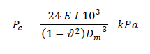
where:
This equation can be re-written in terms of lateral stiffness and is suitable for use with both plain and structured wall pipes:
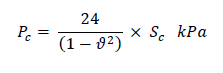
Sc is the calculated stiffness for pressure pipes. For most non-pressure pipes (DWV, Stormwater) a stiffness class or SN forms part of the classification system and this can be substituted in the formula for Sc. For other pipes, appropriate values are given in Table 11.
NOTE: The stiffness values in the tables are calculated on the basis of minimum wall thickness at any point. Since the stiffness is a function of the mean wall thickness, it is statistically not possible for these values to be realised in practice, and the real stiffness will be significantly greater. Based on known process capabilities the mean wall thickness could reasonably be expected to be at least 5% above minimum and the stiffness correspondingly 16% higher than the figures above.
The stiffness is related to the effective modulus, which varies with the loading condition (short or long term), and also with temperature. For long term loading and/or elevated temperatures, the critical buckling pressure should be multiplied by a correction factor, Fc, to take the variation in modulus into account. Appropriate values of the temperature/loading time correction factor are given in the tables below.
Table 1a
| Sc for PVC & PVC-M pressure pipes | |||
| AS/NZS 1477 | AS/NZS 1477 | AS/NZS 4675 | |
| PVC<=150 | PVC>150 | PVC-M | |
| E (MPa) | 3200 | 3200 | 3000 |
| PN 4.5 | 2.3 | 1.6 | – |
| PN 6 | 5.4 | 3.9 | 2.6 |
| PN 9 | 18.3 | 13.1 | 4.3 |
| PN 12 | 43.3 | 31.0 | 10.0 |
| PN 15 | 84.5 | 60.5 | 19.7 |
| PN 16 | 102.6 | 73.4 | 23.9 |
| PN 18 | 146.1 | 104.5 | 34.0 |
| PN 20 | 200.4 | 143.3 | – |
Table 1b
| Sc for PVC-O pressure pipes | |||
| AS 4441 PVC-O | |||
| E (MPa) | 4000 | 4000 | 4000 |
| Material Class | PVC-O 400 | PVC-O 450 | PVC-O 500 |
| PN 10 | 2.7 | 1.9 | 1.3 |
| PN 12 | 5.2 | 3.7 | 2.5 |
| PN 16 | 10.9 | 7.8 | 5.2 |
| PN 20 | 21.3 | 15.2 | 10.2 |
Table 1c
| Sc or SN for DWV pipes | |||
| DN | AS/NZS 1260 | ||
| 32 | 45.3 | ||
| 40 | 31.4 | ||
| 50 | 18.5 | ||
| 65 | 18.3 | ||
| 80 | 13.0 | ||
| 100 | 6 and 10 | ||
| >100 | 4 and 8 | ||
Value of Fc
The material modulus for plastics varies with time and temperature. The factor, Fc, in the buckling formula is used to account for these variations. Examples are as follows:
Table 2
| Loading Term | Temperature | ||
| 20°C | 30°C | 40°C | |
| Short Term – e.g. water surges (seconds/minutes) | 1 | 0.96 | 0.93 |
| Medium Term – e.g. concrete work (hours) | 0.81 | 0.75 | 0.66 |
| Long Term – (day/month) | 0.69 | 0.63 | 0.56 |
| Permanent – e.g. ground water (50 years) for PVC and PVC-M | 0.37 | 0.28 | 0.18 |
| Permanent – e.g. ground water (50 years) for PVC-O | 0.44 | 0.33 | 0.22 |
Temperature Selection
In determining temperatures, the average temperature over the period in question should be applied, i.e. for long term effects, the long-term average should be used. In mass concrete encasement applications, the temperature rise during setting may be significant. The curing of cement compounds is an exothermic reaction. This, in combination with the relatively low thermal conductivity of concrete, means that the reaction can result in a large rise in temperature in the interior of a concrete mass. There are a number of factors which affect the rate of heat evolution such as, the composition of cement used, the cement content of the mix and the ambient temperature. Because of these variables, a conservative figure for temperature is recommended for concrete encasement applications. Of course, the period of concern is the time before the concrete is hardened, when it exerts an external pressure on the pipe. After this time, further heat evolution and temperature rise will be irrelevant to the buckling situation. If the pipe can be filled with water, the internal pressure will counter balance the external pressure to some extent, and the thermal mass of the water will help keep the pipe temperature down. If additional pressure can be applied with a stand pipe, or the water can be circulated, these measures will further assist. PVC-O pipes need special consideration if setting in concrete due to reversion at elevated temperatures. For more information on concrete encasement and grouting, refer to Vinidex Technical Note VX-TN12J.
Structured wall pipes
In many applications, structured wall pipes and plain wall pipes of equivalent stiffness will exhibit the same resistance to buckling and can be used interchangeably, as seen in the above equation. However, there are some situations in which some structured wall pipes will not behave identically. One example of this is for concrete encasement applications to form a void. As noted above, there is a temperature rise associated with concrete setting. For a foam-core pipe, the thin external structural layer will rapidly heat up leading to a loss in strength. This is exacerbated by the reduction in heat dissipation through the insulating foam core of the pipe. To a certain extent, this applies also to Ultra-Rib where the structural ribs, surrounded by concrete, may rise in temperature to a greater extent than the through thickness of a solid wall pipe. Of course a sandwich construction pipe with a solid PVC core will perform in the same way as a solid wall pipe and would be equally suitable for this application.
Effect of Ovality
Initial ovality of a pipe will reduce the critical buckling pressure. 2
The reduction can be calculated by multiplying the critical buckling pressure, Pc, by a correction factor, C1 which is calculated as follows:
For an oval pipe with,
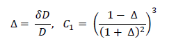
where: dD = the difference between the maximum outside diameter and the mean outside diameter; and D = the mean outside diameter Values for C1 are summarised in the following table:
| Ovality % | Reduction factor, C1, on Pc |
| 0 | 1 |
| 1 | 0.91 |
| 2 | 0.84 |
Note that these reductions apply to inherent initial ovality as distinct from induced ovality, ie., where ovality has been induced by some external (constant strain) source, as in deflection induced by soil loadings, the pipe is already in a state of elastic strain, and the resistance to buckling is degraded far less. In this case, the correction factor C2 is used as given in the following table:
| Diametral Deflection % | Reduction factor, C2, on Pc |
| 0 | 1 |
| 1 | 0.99 |
| 2 | 0.97 |
| 5 | 0.93 |
| 10 | 0.86 |
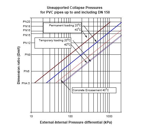
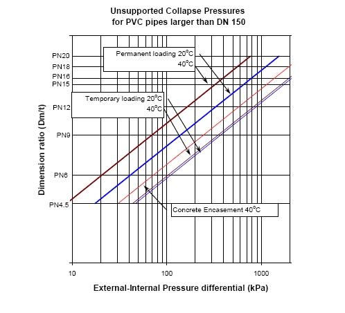
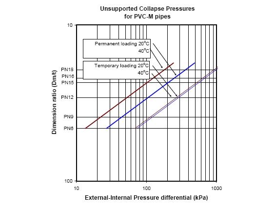
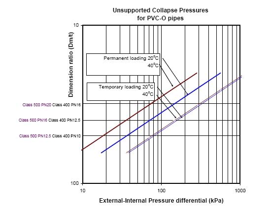
Critical pressures for PVC Pipe
The unsupported collapse pressures for standard PVC, PVC-O and PVC-M pressure pipes for a range of operating conditions are shown in the following graphs.
NOTE: Pipe wall thickness has a major influence on the critical buckling pressure. Therefore PVC-O and PVC-M pipes will not have the equivalent resistance to unsupported collapse as PVC-U pipes of the same pressure class.
Notes:
- Factor of Safety: No factor of safety is incorporated in the above graphs. Initial out-of-round or other lateral loads may reduce the collapse pressure.
- Vacuum Stability: For PVC-U pipes, PN 4.5 collapse pressure for short-term conditions is 6.1m, and this class should not be used for pressure lines likely to be subjected to negative surging. PN 6 is stable against full vacuum (10m).
Supported Collapse Pressure
Support against buckling is provided by end constraints, fittings or special purpose stiffening rings at intervals around the pipe. Effective support reduces as distance from a stiffened section increases and should be considered zero at a distance of seven diameters.
A buried pipe derives support against buckling from stable soil surround, provided it is properly placed and compacted, with no voids, around the pipe, and cannot subsequently be removed or leached away. Granular material should be used. Gravel is best. Coarse sand is good, provided it can’t be washed out. Compressible material such as clay soil is dangerous. Particular attention should be paid to the soil characteristics and shear strength when flooded. If the saturated shear strength is low, totally hydrostatic conditions must be assumed. Some sands can have low wet shear (quick sand is an extreme example).
For stable soil surround, the effective buckling pressure may be computed from:
![]()
where E’ is the soil modulus in MPa. For values of E’, refer to AS/NZS 2566.1
For shallow burial, full support is not developed since buckling can occur by vertical lifting of the soil cover. AS/NZS 2566.1 specifies that for cover heights less than 0.5m, Pc be used to evaluate the potential for buckling. The soil cover required to suppress this type of failure is diameter dependent, and for diameters greater than 500 mm, it is recommended that Pc be used for covers less than one diameter. Where cover heights are greater than or equal to 0.5m, the greater of Pc and Pb should be used. In both cases, an appropriate factor of safety needs to be incorporated.
Factors of Safety
The equations and graphical representations predict actual collapse pressures. No factor of safety is incorporated and designers should decide on an appropriate factor based on service conditions, consequences of failure and predictive uncertainty. AS/NZS 2566.1 specifies a factor of safety of 2.5 unless the designer specifies an alternative. A lower factor of safety should only be specified where conditions and performance can be predicted with confidence. For example, in a calculation of unsupported buckling of a pipe under vacuum, a factor of 1.5 may be appropriate.
Footnotes
1. For plain wall pipes, this can be calculated from the equation:
![]()
2. The effect of initial ovality may be compensated for by the fact that the stiffness of pressure pipes given in table 1a above is based on the minimum wall thickness specified in AS/NZS 1477. In practice, the minimum mean wall thickness of the pipe will always exceed Tmin so actual stiffness will be higher.