

Water Hammer
Water hammer is a temporary change in pressure in a pipeline due to a change in the velocity of flow in a pipe with respect to time, e.g. a valve opens or closes, or a pump starts or stops. Accidental events such as a pipe blockage can also be a cause. The effects are exacerbated by:
- Fast closing/stopping valves/pumps
- High water velocities
- Air in the line
- Poor layout of the pipe network, positioning of pumps, etc.
Note that water hammer pressure may be positive or negative. Both can be detrimental to pipe systems; not only pipes, but pumps, valves and thrust supports can be damaged. Negative pressures can cause ‘separation’ (vacuum formation), with very high positive pressures on ‘rejoinder’ (collapse of the vacuum). For these reasons, water hammer should be eliminated as far as possible.
Water hammer pressures can be reduced by:
- Controlling and slowing valve and pump operations
- Reducing velocities by using larger diameter pipes
- Using pipe materials with lower elastic modulus
- Astute layout of network, valves, pumps and air valves
- Fast-acting pressure relief valves
It is beyond the scope of this manual to give a complete description of water hammer analysis and mitigation. However, it is appropriate to highlight some important aspects related to plastics pipes.
Celerity
Celerity is the speed (expressed in metres per second) that the pressure waves travel in a closed circuit. This should not be confused with the velocity of the water.
This is a function of the pipe geometry (dimension ratio) and material and may be estimated from:
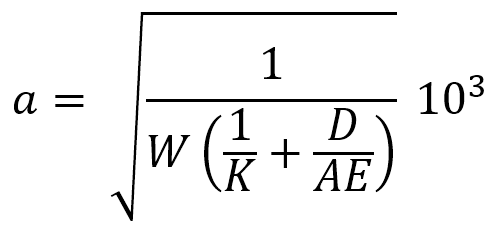 or
or
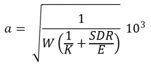
where:
The wave celerity induced in PVC and PE pipes are shown in the Tables below. As plastics have a celerity much lower than that of metallic pipes, analyses for metallic pipes should not be used to check PVC or PE pipe classes.
Dimension Ratio (DR) and Celerity (a)
| PN | PVC-U | |||
| ≤ DN 150 | > DN 175 | |||
| DR | a (m/s) | DR | a (m/s) | |
| 4.5 | 48.9 | 252 | 54.7 | 239 |
| 6 | 36.7 | 290 | 41 | 274 |
| 9 | 24.4 | 351 | 27.3 | 333 |
| 12 | 18.3 | 402 | 20.5 | 381 |
| 15 | 14.7 | 445 | 16.4 | 423 |
| 16 | 13.8 | 458 | 15.4 | 436 |
| 18 | 12.2 | 483 | 13.7 | 460 |
| 20 | 11.0 | 506 | 12.3 | 482 |
| MRS/PN | PVC-O – All sizes | |
| DR | a (m/s) | |
| 400/12.5 | 40 | 309 |
| 500/16 | 40 | 309 |
| 500/20 | 32 | 344 |
| SDR | PE 80 | PE 100 |
| a (m/s) | a (m/s) | |
| 41 | 160 | 190 |
| 33 | 170 | 210 |
| 26 | 190 | 240 |
| 21 | 220 | 260 |
| 17 | 240 | 290 |
| 13.6 | 270 | 320 |
| 11 | 300 | 360 |
| 9 | 330 | 390 |
| 7.4 | 360 | 430 |
For buried pipes, increase the wave celerity (a) by 7%.
The advantage of a low celerity can be demonstrated by Joukowsky’s Law, which gives an estimate for the water hammer pressure rise due to instantaneous valve closure (Pa).
![]() where:
where:
This equation should NOT be used for design purposes. Water hammer analysis is fairly complex and computer analysis by a competent consultant is recommended wherever it is suspected that water hammer may be significant.
Pipe Response
Selection of class should be based on peak operating pressures including water hammer. Control devices may be useful in reducing peak pressures and enable a more economic pipe class to be used.
The response of the pipe to occasional abnormal pressures, for example, due to the failure of protective devices, is important.
PVC and PE have a high factor of safety on short term stress effects and is able to withstand occasional events at higher than normal pressures. This advantage should be considered when determining the validity of basing a design purely on the pressures induced by events that may be rare in the design lifetime, e.g. power failure on a pump.