

PE Temperature Considerations
Effect of Temperature on Pressure Rating
The physical properties of Vinidex PE pipes are related to a standard reference temperature of 20°C. Where physical property values are quoted to ISO and DIN Standard test methods, these are for the 20°C condition, unless otherwise quoted.
PE pipes may be used at operating temperatures between -40°C and +80°C. For temperatures less than 20°C it is convention to use the 20°C hydrostatic design stress. Below freezing, additional care may be required as the impact strength of PE is reduced. Wherever PE pipelines operate at elevated temperatures above 20°C, the pressure ratings (PN) must be reduced.
The temperature to be considered for the re-rating is the pipe material service temperature, and the actual operating conditions for each specific installation must be evaluated.
The temperature of the pipe wall may be based on either:
- the assumption of constant temperature;
- the determination of an average service temperature where temperature variations are likely to be predictable; or
- the maximum temperature less 10°C for installations where large unpredictable temperature variations are likely to occur.
The average material temperature may be determined:
- across the pipe wall, with the average temperature taken as the mean of the internal and external pipe surface temperatures where a temperature differential exists between the fluid and the external environment. The pressure and temperature condition should be checked were flow is stopped for prolonged periods as the temperature may equalise in this circumstance; or
- with respect to time, the average temperature may be considered to be the weighted average of temperatures in accordance with the proportion of time spent at each temperature under operational pressures:
Tm = T1 L1 + T2 L2 + … + Tn Ln
where Ln = proportion of life spent at temperature Tn
This approximation is reasonable provided the temperature variations from the mean do not exceed ± 10°C which is generally the case for pipes buried below 300 mm.
For long length installations a temperature gradient may exist along the length of the pipe line. This gradient will be dependent upon site conditions, and the fluid being carried will approach the ambient temperature of the surrounds. The rate of temperature loss will be determined by inlet temperature, fluid flow rate, soil conductivity, ambient temperature and depth of burial. As these factors are specific to each installation, the temperature gradient calculations are complex.
In addition, as PE is an oxidising material, the lifetime of some grades will be limited by elevated temperature operation. The tables below give temperature rerating data for Vinidex pipes made to AS/NZS 4130. In these tables, allowable working pressures are consistent with PIPA Guideline POP013 – Temperature Rerating of PE Pipes and assume continuous operation at the temperatures listed for pipes conveying water. Extrapolation limit is maximum allowable extrapolation time in years, based on data analysis in accordance with ISO 90801, and at least two years of test at 80°C for PE80B and PE100. Actual product life may well be in excess of these values. The performance of compounds used in the manufacture of Vinidex pipes to AS/NZS 4130 has been verified by appropriate data analysis.
Where pipes are used for drinking water applications with higher disinfectant residuals, particularly at elevated temperatures, further consideration may be required. See Chemical Resistance of PE Pipes.
Note that the rerating factors the temperature rating Tables below differ from the suggested temperature rerating sub-factors in the previous Table for design factors in that they are PE material specific and cover a wider range of temperatures. Where the Table for design factors for water and sewerage pipe systems is being used as a means of determining an alternative overall design factor, and the pipe is conveying water, it may be appropriate to substitute the factors in the temperature ratings Tables below for the more general temperature sub-factors in that Table.
1. ISO 9080 – Plastics piping and ducting systems – determination of long-term hydrostatic strength of thermoplastics materials in pipe form by extrapolation.
Temperature Rating Tables
PE80
| Temp
(°C) |
Extrapolation limit years
Lmin |
Design Factor | Maximum allowable operating pressure MAOP (m head water) |
|||||||
| PN3.2 | PN4 | PN6.3 | PN8 | PN10 | PN12.5 | PN16 | PN20 | |||
| 20 | 100 | 1 | 32 | 40 | 63 | 80 | 100 | 125 | 160 | 200 |
| 25 | 100 | 1 | 32 | 40 | 63 | 80 | 100 | 125 | 160 | 200 |
| 30 | 100 | 1.2 | 27 | 33 | 53 | 67 | 85 | 107 | 133 | 167 |
| 35 | 100 | 1.3 | 25 | 31 | 49 | 62 | 78 | 98 | 123 | 154 |
| 40 | 100 | 1.3 | 25 | 31 | 49 | 62 | 78 | 98 | 123 | 154 |
| 45 | 100 | 1.4 | 23 | 29 | 46 | 57 | 73 | 91 | 114 | 143 |
| 50 | 36 | 1.6 | 20 | 25 | 40 | 50 | 63 | 80 | 100 | 125 |
| 55 | 24 | 1.7 | 19 | 24 | 38 | 47 | 60 | 75 | 94 | 118 |
PE100
| Temp
(°C) |
Extrapolation limit years
Lmin |
Design Factor | Maximum allowable operating pressure MAOP (m head water) |
|||||||
| PN4 | PN6.3 | PN8 | PN10 | PN12.5 | PN16 | PN20 | PN25 | |||
| 20 | 100 | 1 | 40 | 64 | 80 | 100 | 127 | 160 | 200 | 250 |
| 25 | 100 | 1.1 | 36 | 58 | 73 | 91 | 115 | 145 | 182 | 227 |
| 30 | 100 | 1.1 | 36 | 58 | 73 | 91 | 115 | 145 | 182 | 227 |
| 35 | 50 | 1.2 | 33 | 53 | 67 | 83 | 106 | 133 | 167 | 208 |
| 40 | 50 | 1.2 | 33 | 53 | 67 | 83 | 106 | 133 | 167 | 208 |
| 45 | 35 | 1.3 | 31 | 49 | 62 | 77 | 99 | 123 | 154 | 192 |
| 50 | 22 | 1.4 | 29 | 46 | 57 | 71 | 91 | 114 | 143 | 179 |
| 55 | 15 | 1.4 | 29 | 46 | 57 | 71 | 91 | 114 | 143 | 179 |
Pipe Design for Variable Operational Conditions
The following examples assist in the design and selection of polyethylene pipes for variable operating conditions.
Given Operating Conditions:
Pressure/Temperature/Time Relationship
Determine
- Material
- Class of pipe
- Life
Steps
- Assume a material
- Determine Class from Temperature Rating Table
Note: For brief periods at elevated temperature it may be appropriate to decrease the safety factor to a value of x, i.e. multiply the working pressure by:
1.25/x - By the following process, assess whether life is ‘used up’.
For each combination of time and temperature, estimate the proportion of life ‘used up’ by using the time/temperature relationships in the table. If the proportion is less than unity, the material is satisfactory.
Example
Pumped system normally working at a maximum head, including surge of 60m. At startup, the mean pipe wall temperature is 55°C, dropping to 35°C after 1 hour. Pump operation is for 10 hours per day, with a system life of 15 years.
- Assume PE 80
- Determine Pipe Class
The worst situation is operation at 55°C. From the PE80 Table, PN10 pipe at 55°C has an allowable working head of 60m. PN10 pipe is therefore satisfactory. - Determine Life
Total time at 55°C = 1 x 365 x 15 = 5475h = 0.625y.
From the PE80 Table, Lmin for 55°C is 24 years, therefore proportion of time used is:
0.625/24 = 0.026 = 2.6%
Total time at 35°C = 9 x 365 x 15 = 49275h = 5.625y.
From the table, Lmin for 35°C is 100 years, therefore proportion of time used is:
5.625/100 = 0.056 = 5.6%
Total proportion is 8.2% of life used in 15 years (6.25 years actual operation).
The data in the tables are obtained from the use of ISO 13761 and ISO/DIS 9080 and are appropriate for compounds typically used by Vinidex.
Expansion and Contraction
Expansion and contraction of PE pipes occurs with changes in the pipe material service temperature.
This is in common with all pipe materials and in order to determine the actual amount of expansion or contraction, the actual temperature change, and the degree of restraint of the installed pipeline need to be known.
For design purposes, an average value of 2.0 x 10⁻⁴ /°C for Vinidex PE pipes may be used.
The relationship between temperature change and length change for different PE grades is as shown in the Figure below.
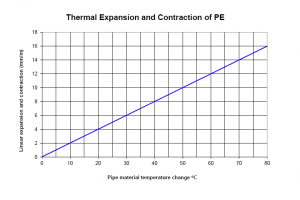
Worked Example
A 100 metre long PE100 pipeline operates during the day at a steady temperature of 48°C and when closed down at night cools to an ambient temperature of 18°C. What allowance for expansion/contraction must be made?
- The temperature change experienced = 48 – 18 = 30°C.
- The thermal movement rate (Figure 4.5) in mm/m for 30°C= 6.0 mm/m.
- The total thermal movement is then 6.0 x 100 = 600 mm.
Where pipes are buried, the changes in temperature are small and slow acting, and the amount of expansion/contraction of the PE pipe is relatively small. In addition, the frictional support of the backfill against the outside of the pipe restrains the movement and any thermal effects are translated into stress in the wall of the pipe.
Accordingly, in buried pipelines the main consideration of thermal movement is during installation in high ambient temperatures. Under these conditions the PE pipe will be at its maximum surface temperature when placed into a shaded trench, and when backfilled will undergo the maximum temperature change, and hence thermal movement. In these cases, the effects of temperature.
In these cases the effects of temperature change can be minimised by snaking the pipe in the trench for small sizes (up to DN110) and allowing the temperature to stabilise prior to backfilling.
For large sizes, the final connection should be left until the pipe temperature has stabilised.
Above ground pipes require no expansion/contraction considerations for free ended pipe or where lateral movement is of no concern on site. Alternatively, pipes may be anchored at intervals to allow lateral movement to be spread evenly along the length of the pipeline.
Where above ground pipes are installed in confined conditions such as industrial or chemical process plants the expansion/contraction movement can be taken up with sliding expansion joints. Where these cannot be used due to the fluid type being carried ( such as slurries containing solid particles ) the advice of Vinidex design engineers should be sought for each particular installation.