
PVC Thrust Support
An imbalanced thrust is developed by a pipeline at:
- Direction changes (>10°), e.g. tees and bends.
- Changes in pipeline size at reducers.
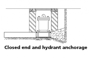
- Pipeline terminations, e.g. at blank ends and valves.
- The support system or soil must be capable of sustaining such thrusts.
Pressure thrust results from internal pressure in the line acting on fittings. Velocity thrust results from inertial forces developed by a change in direction of flow. The latter is usually insignificant compared to the former.
Pressure Thrust
The pressure thrust developed for various types of fittings can be calculated as follows:
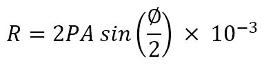
where:
The design pressure used should be the maximum pressure, including water hammer, to be applied to the line. This will usually be the field test pressure.
Pressure Thrust at Fittings in kN for each 10 metres Head of Water
Series 1 Pipe
| Size | Area | Bends | Tees Ends Valves | |||
| DN | (mm2) | 11¼º | 22½º | 45º | 90º | |
| 15 | 363 | 0.01 | 0.01 | 0.03 | 0.05 | 0.04 |
| 20 | 568 | 0.01 | 0.02 | 0.04 | 0.08 | 0.06 |
| 25 | 892 | 0.02 | 0.03 | 0.07 | 0.12 | 0.09 |
| 32 | 1410 | 0.03 | 0.05 | 0.11 | 0.20 | 0.14 |
| 40 | 1840 | 0.04 | 0.07 | 0.14 | 0.26 | 0.18 |
| 50 | 2870 | 0.06 | 0.11 | 0.22 | 0.40 | 0.28 |
| 65 | 4480 | 0.09 | 0.17 | 0.34 | 0.62 | 0.44 |
| 80 | 6240 | 0.12 | 0.24 | 0.47 | 0.87 | 0.61 |
| 100 | 10300 | 0.20 | 0.39 | 0.77 | 1.43 | 1.01 |
| 125 | 15500 | 0.30 | 0.59 | 1.16 | 2.15 | 1.52 |
| 150 | 20200 | 0.39 | 0.77 | 1.52 | 2.80 | 1.98 |
| 200 | 40000 | 0.77 | 1.53 | 3.00 | 5.55 | 3.92 |
| 225 | 49400 | 0.95 | 1.89 | 3.71 | 6.85 | 4.84 |
| 250 | 61900 | 1.19 | 2.37 | 4.65 | 8.58 | 6.07 |
| 300 | 78400 | 1.51 | 3.00 | 5.88 | 10.87 | 7.69 |
| 375 | 126000 | 2.42 | 4.82 | 9.46 | 17.47 | 12.36 |
Series 2 Pipe
| Size | Area | Bends | Tees Ends Valves | |||
| DN | (mm2) | 11¼º | 22½º | 45º | 90º | |
| 100 | 11700 | 0.23 | 0.46 | 0.89 | 1.65 | 1.17 |
| 150 | 24800 | 0.48 | 0.96 | 1.89 | 3.5 | 2.47 |
| 200 | 42500 | 0.83 | 1.65 | 3.24 | 5.99 | 4.24 |
| 250 | 52900 | 1.04 | 2.06 | 4.04 | 7.47 | 5.28 |
| 300 | 93700 | 1.84 | 3.66 | 7.17 | 13.25 | 9.37 |
| 375 | 142700 | 2.8 | 5.57 | 10.92 | 20.18 | 14.27 |
Velocity Thrust
Applies only at changes in direction of flow (kN):
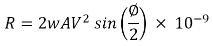
where:
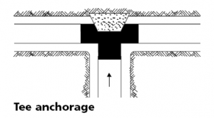
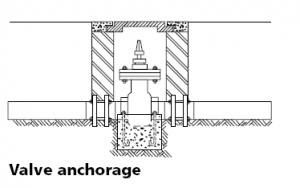
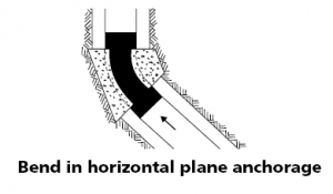
Thrust Blocks
Concrete thrust blocks are usually required to transfer unbalanced forces in buried pipelines to the surrounding soil. See Installation Guidelines for construction of thrust blocks.
To determine the bearing area of the thrust block required, divide the resultant thrust by the bearing capacity of the soil.
The bearing capacity of the soil is dependent on the mode of failure. For deep situations, compressive characteristics will govern and a guide to the appropriate design bearing loads is given in the table below.
For shallow cover, shearing slip failure can occur and bearing loads are very much reduced. For cover less than 600 mm, or less than three pipe diameters, or if the ground is potentially unstable, e.g. embankment conditions, a complete soil analysis should be carried out.
Slip failure may be avoided by extending the thrust block downwards with reinforcement against bending loads.
Safe Compressive Bearing Load
| Soil Description | USBR Soil Classification see ASTM D2478 | Soil Bearing Strength (kN/m2) for cover height *h | |||
| 0.75m | 1.0m | 1.25m | 1.5m | ||
| Well graded gravel-sand mixtures, well graded sands, little or no fines | GW, SW | 57 | 76 | 95 | 114 |
| Poorly graded gravels and gravel-sand mixtures, Poorly graded sands, little or no fines | GP,SP | 48 | 64 | 80 | 97 |
| Silty gravels, gravel-sand-silt mixtures, silty sands, sand-silt mixtures | GM, SM | 48 | 64 | 80 | 96 |
| Clayey gravels, gravel-sand-clay mixtures, Clayey sands, sand-clay mixtures | GC, SC | 79 | 92 | 105 | 119 |
| Inorganic clays of low to med plasticity, gravelly clays, sandy clays, silty clays, lean clays | CL | 74 | 85 | 95 | 106 |
| Inorganic silts, very fine sands, rock flour, silty or clayey fine sands | ML | 69 | 81 | 93 | 106 |
| Organic clays of medium to high plasticity | OH | 0 | 0 | 0 | 0 |
| Rock | 240 | 240 | 240 | 240 | |
| *h = height of soil cover measured from centreline | |||||
Example:
Thrust block design for a DN100 Tee operating at 120 m head in clayey sand soil, *h=1.0m.
Resultant force = 1.01 x 12 = 12.1 kN
Bearing Area = 12.1 / 92 = 0.13 m2
That is, a bearing area 0.25 m high and 0.55 m wide would be suitable.
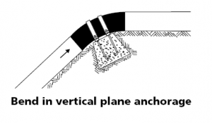
Vertical Thrusts
For resultant upward forces, the mass of the thrust block plus any soil directly above the pipe can be taken as the counterbalancing force, provided the overburden can reasonably be expected to remain there for the life time of the pipeline. It is often better to bury the pipe deeper than to add more concrete to counterbalance an upward thrust.
Figure – Thrust Blocks