

PVC Below Ground Installation
To be read in conjunction with AS/NZS 2032 and AS/NZS 2566.2
Preparing the Pipes
Before installation, each pipe and fitting should be inspected to see that its bore is free from foreign matter and that its outside surface has no large scores or any other damage. The limit for allowable damage to the external surface away from the sealing surfaces is:
- For pressure pipes, 10% of wall thickness up to a maximum of 1mm.
- For non-pressure pipes, 10% of wall thickness. For sandwich construction pipes up to a maximum of the solid skin thickness.
Pipe ends should be checked to ensure that the spigots and sockets are free from damage. The limit for allowable damage to the sealing surfaces of rubber ring jointed pressure pipes
- For rubber ring jointed pressure pipes, 0.5mm
- For non-pressure pipes, nil when viewed without magnification.
Pipes of the required diameter and class should be identified and matched with their respective fittings and placed ready for installation.
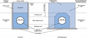
Preparing the Trench
PVC pipe is likely to be damaged or deformed if its support by the ground on which it is laid is not made as uniform as possible. The trench bottom should be examined for irregularities and any hard projections removed.
Trench Widths
A trench should be as narrow as practical but adequate to allow space for working area and for jointing, compaction of the side support and inspection. It should be not less than 200 mm wider than the outside diameter of the pipe irrespective of soil condition.
Wide Trenches
For deep trenches where significant soil loading may occur, the trench should not exceed the widths given in the Table below without further investigation.
Table Recommended Trench Widths
| Size DN | Minimum | Maximum |
| (mm) | (mm) | |
| 100 | 320 | 800 |
| 125 | 340 | 825 |
| 150 | 360 | 825 |
| 200 | 525 | 900 |
| 225 | 560 | 925 |
| 250 | 580 | 950 |
| 300 | 745 | 1000 |
| 375 | 825 | 1200 |
Unstable Conditions
Where a trench, during or after excavation, tends to collapse or cave in, it is considered unstable. If the trench is located, for instance, in a street or a narrow pathway and it is therefore impractical to widen the trench, support should be provided for the trench walls in the form of timber planks or other suitable shoring.
Alternatively, the trench should be widened until stability is reached. At this point, a smaller trench may then be excavated in the bottom of the trench to accept the pipe. In either case do not exceed the maximum trench width at the top of the pipe unless allowance has been made for the increased load.
Trench Depths
The recommended minimum trench depth is determined by the loads imposed on the pipe such as the mass of backfill material, the anticipated traffic loads and any other superimposed loads. The depth of the trench should be sufficient to prevent damage to the pipe when the anticipated loads are imposed upon it.
Minimum Cover
Trenches should be excavated to allow for the specified depth of bedding, the pipe diameter and the minimum recommended cover, overlay plus backfill, above the pipes. The Table below provides recommendations for minimum cover.
Minimum Cover
| Loading Condition | Cover, H |
| (mm) | |
| Not subject to vehicular loading | 300 |
| Subject to vehicular loading – (a) no carriageways; (b) sealed carriageways; (c) unsealed carriageways |
450 600 750 |
| Pipes in embankments or subject to construction equipment loading | 750 |
The above cover requirements will provide adequate protection for all classes of pipe. Where it is necessary to use lower covers, several options are available.
- Use a high quality granular backfill, e.g. crushed gravel or road base.
- Use a higher class of pipe than required for normal pressure or other considerations.
- Provide additional structural load bearing bridging over the trench. Temporary steel plates may be used in the case of construction loads.
Bedding Material
Preferred bedding materials are listed in AS/NZS 2566.2 as follows:
- Suitable sand, free from rock or other hard or sharp objects that would be retained on a 13.2 mm sieve.
- Crushed rock or gravel of approved grading up to a maximum size of 14 mm.
- The excavated material may provide a suitable pipe underlay if it is free from rock or hard matter and broken up so that it contains no soil lumps having any dimension greater than 75 mm which would prevent adequate compaction of the bedding.
- Controlled low strength materials (CLSM).
The suitability of a material depends on its compatibility. Granular materials (gravel or sand) containing little or no fines, or specification graded materials, require less compactive effort, and are preferred. Sands containing fines, and clays are difficult to compact and should only be used where it can be demonstrated that appropriate compaction can be achieved.
Variations in the hard bed should never exceed 20% of the bedding depth. Absolute minimum underlay should be 75 mm. It may be necessary to provide a groove under each socket to ensure that even support along the pipe barrel is achieved.
Pipe Side Support and Overlay
Material selected for pipe side support should be adequately tamped in layers of not more than 150 mm. Care should be taken not to damage or distort the exposed pipe and to compact evenly on either side of the pipe to the TEPPFA or AS/NZS 2566 design level. The side support materials must be carefully placed around the haunches of the pipes to ensure that the pipes are evenly supported.
Unless otherwise specified, the pipe side support and pipe overlay material used should be identical with the pipe bedding material.
The pipe overlay material should be leveled and tamped in layers to a minimum height of 150 mm above the crown of the pipe. Care should be taken not to disturb the line or grade of the pipeline, where this is critical, by excessive tamping.
Detector tapes, or marker strips, should be laid on top of the overlay once a layer of 150mm soil has been compacted.
Trench Fill
Unless otherwise specified, excavated material from the site should constitute the trench fill.
Gravel and sand can be compacted by vibratory methods and clays by tamping. This is best achieved when the soils are wet. If water flooding is used and extra soil has to be added to the original backfill, this should be done only when the flooded backfill is firm enough to walk on. When flooding the trench, care should be taken not to float the pipe.
PVC Pipes under Roads
PVC pipes can be installed under roads in either the longitudinal or transverse direction.
The type of rock / granular materials specified for road subgrades have a very high soil modulus and offer excellent side support for flexible pipes as well as minimising the effects of dead and live loads. This represents an ideal structural environment for PVC pipes.
Consideration should be given at the time of installation to ensure:
- construction loadings are allowed for;
- the pipes are buried at sufficient depth to ensure they are not disturbed during future realignments or regrading of the road; and
- minimum depths of cover and compaction techniques are observed.
Pipeline Buoyancy
Pipe, under wet conditions, can become buoyant in the trench. PVC pipe, being lighter than most pipe materials, should be covered with sufficient overlay and backfill material to prevent inadvertent flotation and movement. A depth of cover over the pipe of 1.5 times the diameter is usually adequate.
Expansion and Contraction
Pipe will expand or contract if it is installed during very hot or very cold weather, so it is recommended that the final pipe connections be made when the temperature of the pipe has stabilised at a temperature close to that of the backfilled trench.
When the pipe has to be laid in hot weather, precautions should be taken to allow for the contraction of the line which will occur when it cools to its normal working temperature.
For solvent cemented systems, the lines should be free to move until a strong bond has been developed (see Solvent Cement Jointing Procedures) and installation procedure should ensure that contraction does not impose strain on newly made joints.
For rubber ring jointed pipes, if contraction accumulates over several lengths, pull-out of a joint can occur. To avoid this possibility the preferred technique is to back-fill each length, at least partially, as laying proceeds. (It may be required to leave joints exposed for test and inspection.)
It should be noted that rubber ring joint design allows for contraction to occur. Provided joints are made to the witness mark in the first instance, and contraction is taken up approximately evenly at each joint, there is no danger of loss of seal. A gap between witness mark and socket of up to 10 mm after contraction is quite acceptable.
Further contraction may be observed on pressurisation of the line (so-called Poisson contraction due to circumferential strain). Again, this is anticipated in joint design and is quite in order.
For further information and data concerning thermal expansion and contraction, see PVC Temperature Considerations.
Electrical Earthing
PVC piping is a non-conductive material and cannot be used for earthing electrical installations or for dissipating static charges. Local authorities, both water and electrical, should be consulted for their requirements.
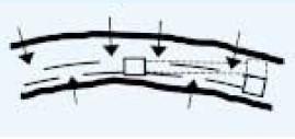
Installing Pipes on a Curve
PVC pipes may be bent during laying to follow a curved path. The minimum bending radius is 300 times the outside diameter for pressure pipes and 150 times the outside diameter for non-pressure pipes.
When installing pipes on a curve, the pipe should be jointed straight and then laid to the curve. Bending of pipes is achieved in practice after each joint is made, by laterally loading the pipe by any convenient means, and fixing in place by compacted soil, or appropriate fixings above ground. The technique used depends on the size and class of pipe involved, as clearly the forces required to induce bending vary over a very large range. For buried lines in good soil, the compaction process can be used to induce bending as illustrated below. Bending aids, crowbars etc. must always be padded to prevent damage to pipes. Permanent point loads are not acceptable.
Significant bending moments should not be exerted on rubber ring joints, since this introduces undesirable stresses in the spigot and socket that may be detrimental to long term performance. To avoid this, reaction supports should be placed adjacent to the socket rather than on the sockets. For buried pipes this also allows the joint to be left open for inspection during testing. Because of this restriction, the length available for bending is less than the full length of the pipe. It is also not practicable to maintain a constant radius of curvature by application of point load forces. The calculations shown in the Table below are derived from beam theory and assume a 5m bending length for calculation of the deflection angle.
Solvent cement jointed pipes may be curved continuously, i.e., bending moments may be transmitted across the joints, but bending may be applied only after full curing, 24 hours for pressure and 48 hours for non-pressure joints. For solvent cement jointed pipelines, the angular deflection figures should be increased by 20%.
Maximum deflection angles, centre displacements and end offsets for 6m PVC pressure pipes
| Nominal size | Force applied at centre span | Forces applied at quarter points | ||||
| DN | Max. deflection angle | Max. Displacement | Max. end offset | Max. deflection angle | Max. Displacement | Max. end offset |
| deg | mm | mm | deg | mm | mm | |
| Minimum radius of curvature/diameter ratio 300 | ||||||
| Series 1 diameters | ||||||
| 15 | 23 | 470 | 1200 | 34 | 650 | 1800 |
| 20 | 18 | 380 | 950 | 27 | 520 | 1400 |
| 25 | 14 | 300 | 740 | 21 | 410 | 1100 |
| 32 | 11 | 240 | 580 | 17 | 330 | 900 |
| 40 | 9.9 | 210 | 520 | 15 | 290 | 790 |
| 50 | 7.9 | 170 | 410 | 12 | 230 | 630 |
| 65 | 6.3 | 130 | 330 | 9.5 | 180 | 500 |
| 80 | 5.4 | 110 | 280 | 8.1 | 160 | 420 |
| 100 | 4.2 | 88 | 220 | 6.3 | 120 | 330 |
| 125 | 3.4 | 71 | 180 | 5.1 | 98 | 270 |
| 150 | 3 | 63 | 160 | 4.5 | 86 | 240 |
| 175 | 2.4 | 50 | 130 | 3.6 | 69 | 190 |
| 200 | 2.1 | 44 | 110 | 3.2 | 61 | 170 |
| Series 2 diameters | ||||||
| 100 | 3.9 | 82 | 200 | 5.9 | 110 | 310 |
| 150 | 2.7 | 56 | 140 | 4 | 78 | 210 |
| 200 | 2.1 | 43 | 110 | 3.1 | 59 | 160 |
Note: Beam theory is applicable to small deflections and figures for small bore pipes with centreline displacements greater than 5% of span should be treated as very approximate
Thrust Blocks
Underground PVC pipelines jointed with rubber ring joints require concrete thrust blocks to prevent movement of the pipeline when a pressure load is applied. In some circumstances, thrust support may also be advisable in solvent cement jointed systems. Uneven thrust will be present at most fittings. The thrust block transfers the load from the fitting, around which it is placed, to the larger bearing surface of the solid trench wall.
Construction of Thrust Blocks
Concrete should be placed around the fitting in a wedge shape with its widest part against the solid trench wall. Some forming may be necessary to achieve an adequate bearing area with a minimum of concrete. The concrete mix should be allowed to cure for seven days before pressurisation.
A thrust block should bear firmly against the side of the trench and to achieve this, it may be necessary to hand trim the trench side or hand excavate the trench wall to form a recess. The thrust acts through the centre line of the fitting and the thrust block should be constructed symmetrically about this centre line. See Thrust Support for design of thrust block size.
PVC pipes and fittings should be covered with a protective membrane of PVC, polyethylene or felt when adjacent to concrete so that they can move without being damaged. See Above Ground Installation for more information.
Pipelines on Steep Slopes
Two problems can occur when pipes are installed on steep slopes, i.e. slopes steeper than 20% (1:5).
- The pipes may slide downhill so that the witness mark positioning is lost. It may be necessary to support each pipe with some cover during construction to prevent the pipe slipping.
- The embedment material around the pipe may be scoured out by water movement in the trench. Clay stops, or sandbags should be placed at appropriate intervals above and below the pipe to stop erosion of the backfill.
Where bulkheads are used, one restraint per pipe length, placed adjacent to the socket, is considered sufficient for all slopes.